Technology & Product
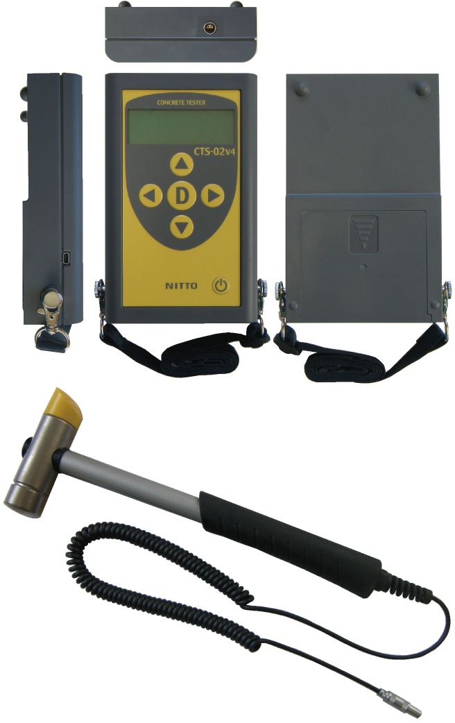
CTS-02v4
CTS-02v4(Concrete Test and Surveyor)
Non-destructive testing equipment for primary screening
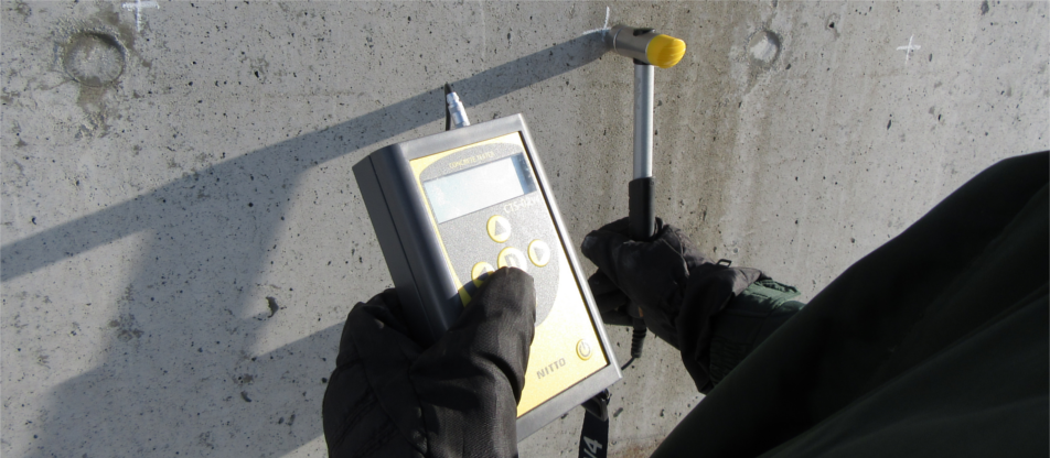
The CTS (Concrete Tester) was developed in response to the 1999 accident in which a chunk of concrete fell from a tunnel. Conventional concrete testing methods have problems such as relatively low accuracy, the need for corrections to measurement data, a lack of objectivity in the results, and no data being retained. The CTS is a simple non-destructive testing device that solves these problems. It displays an estimated compressive strength value as a number immediately after hitting the concrete, allowing you to quickly understand the condition of the concrete, and the measured data can be accessed by connecting to a computer.
Applications
□ Estimation for compressive strength of concrete (Normal to High strength concrete)
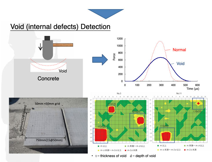
□ Detecting degree of degradation of concrete surface
□ Detecting delamination of concrete surface
□ Detection of aggregate peeling on concrete surfaces
Comparison
■ Comparison on Estimation of Compressive Strength
| CTS | Rebound hammer | |
|---|---|---|
| Estimation accuracy ※Comparison with compression test as 100% based on our experiment |
85% | 50% |
| Applicable range of strength | 10~150N/mm2 | 10~70N/mm2 |
| Data correctionUnnecessary | Unnecessary | Necessary |
| Number of measurement point | 3250 point/day | 1500 point/day |
| Data analysis | 6375 point/day | 1000 point/day |
■ Comparison on detection of delamination of concrete
| CTS | Inspection hammer(hammer sounding test) | |
|---|---|---|
| Judgement criteria | Objective | Subjective |
| Data output | CSV (digital) | Paper (analog) |
Specifications
| Model Name | CTS-02v4(Concrete Test and Surveyer) |
|---|---|
| Applicable Standard | NDIS3434-3 |
| Storage case dimensions | 390mm x 255mm x 120mm |
| Body size | 108mm x 69mm x 42mm |
| Hammer Weight | 380g |
| Waveform Measurement | Sampling clock: 0.5µs Measuring time: 2 ms |
| Power supply | AA Batteries x 4 (for 12 hours) |
| Connection to PC | USB |
| Number of measurement data | Up to approx. 500,000 |
| Accessories | ・USB cable(A – mini B) ・Strap ・Storage case ・AA batteries x 4 ・CD-ROM(Application software, device driver, User manual) |
How to Use
Basic Principle
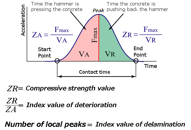
The waveform of impact force in below is obtained by tapping concrete with CTS. This wave form is measured by an accelerometer that installed on the hammer unit. Measured wave form can be divided into two part. The first half of the waveform shows the process that the hammer is pushing on the concrete surface. This process includes plastic deformation first, then elastic deformation of concrete surface. The second half of the waveform is the process that the hammer is rebounding from the concrete surface. In other words, the second half of the waveform is only affected by the characteristics of elasticity of concrete, and compressive strength of the concrete that is not affected by deterioration of concrete surface can be estimated. Besides, degree of deterioration of concrete surface can be determined from the ratio of the first half and the second half of the waveform.
Typical Measured Waveforms
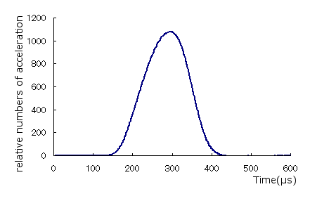
■ Measured waveform of sound concrete
The shape of waveform will be symmetry. Since concrete is not perfectly elastic body, first half of the waveform shall contain an influence of elasticity of surface layer.
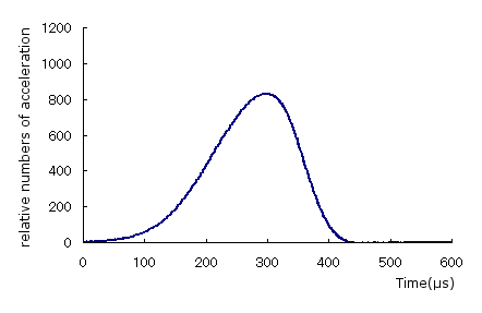
■ Measured waveform of concrete with degraded surface
First half of the waveform will be longer comparing to sound concrete. In this case, first half of the waveform contains an influence of elastic deformation of degraded concrete surface while it is reduced in the second half of the waveform.
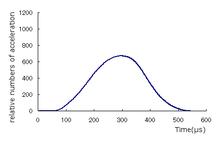
■ Measured waveform of concrete with delamination near the surface (1)
This type of waveform will be measured when delamination is occurred near the surface. The shape of waveform seems like a sound concrete, but peak of the waveform becomes lower and contact time of the hammer becomes longer. As the delaminated concrete surface reacts like a blade spring against hammer blow, maximum impact becomes lower and contact time becomes longer.
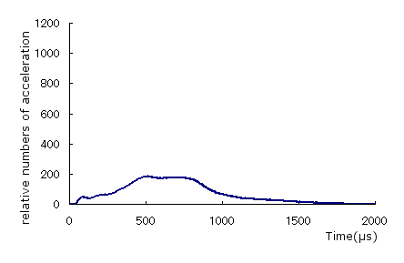
■ Measured waveform of concrete with delamination near the surface (2)
This waveform is obtained when a hammer strikes concrete that is about to spall. Since no reaction force is generated by the hammer strike, a normal waveform cannot be obtained. Note that the horizontal axis (time axis) is significantly different from previous measurements.
CTS Use Cases
Survey of remaining strength of floorboards
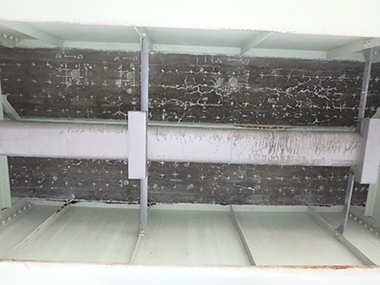
■Reason for the survey
The floorboards had deteriorated significantly due to frost damage, and there was concern that they might fall out.
In order to consider permanent measures or future maintenance policies, a survey was conducted to understand the distribution of compressive strength.
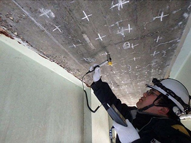
■Survey method
The blocks to be surveyed were selected on-site, and measurement points were marked in a grid pattern at intervals of approximately 200 mm in the axial direction of the bridge and 100 mm in the perpendicular direction. The measurement points were then struck with a concrete tester (CTS-02), and measurements were recorded.
■Survey results
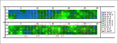
The range of cracks confirmed by visual inspection closely matched the range of relative strength reduction on the strength distribution map, making it clear that deterioration due to frost damage was progressing.
■Responses and measures
As there is concern that localized damage to floorboards may occur, it is advisable to consider implementing emergency measures.